Product Overview
The HS-V500 device is a vehicle-mounted deployment model featuring a metal sheet shell construction. Its core advantages lie in comprehensive coverage and precise control capabilities. Utilizing full-band interference technology, it effectively addresses complex requirements across various signal frequency bands. The premium hardware design not only ensures ultra-long-range interference but also guarantees operational stability in extreme environments.
Product Features
- Full-Frequency Coverage: The strike module features customizable frequency and power settings, achieving comprehensive frequency band coverage and suppression across the 100 MHz to 6 GHz spectrum. Encompasses communication bands including 2G, 3G, 4G, 5G, GPS/GNSS, and WiFi.
- Module Replacement: Equipped with module plug-and-play replacement technology, enabling convenient and rapid replacement, maintenance, and technical iteration. Each module operates independently — direct replacement without affecting other modules.
- Operation Modes: The device can be controlled remotely via network access or operated from close range using mechanical devices, meeting operational requirements across various scenarios.
- Device Management: Equipped with an in-house developed device deployment platform — enables independent control of operation plans, power regulation, and health status queries through network port communication.
- Function Display: The device module features multiple display options including LED and LCD screens, facilitating real-time monitoring of operational status.
- Quality Certification: Products certified under the ISO9001 Quality Management System, ensuring stable and reliable quality.
- Smart Temperature Control: Equipped with an integrated smart temperature control system ensuring prolonged operation of the main unit.
Application Scenarios
This high-power vehicle-mounted strike system is designed for diverse operational scenarios including:
| Drone no-fly zones | Luxury residences | Tourist attractions | Fuel stations / storage |
| Power infrastructure | VIP security (senior officials) | Individual combat operations | Special police units |
| Bomb disposal teams | Counter-terrorism units | Narcotics enforcement | Explosion prevention teams |
| Security checkpoints | Law enforcement missions | Hostage negotiations | Border control operations |
| Military security forces | |||
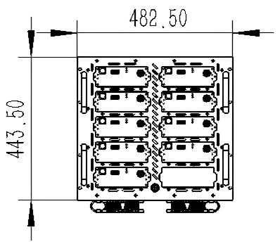
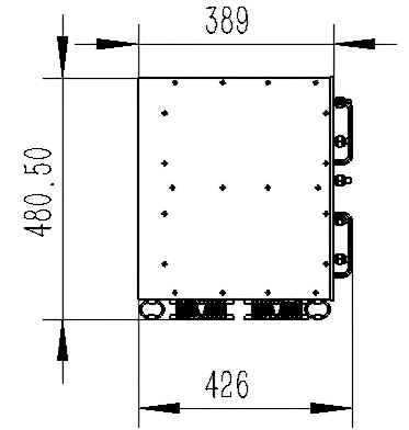
Device Size Diagram
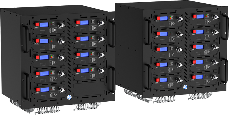
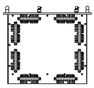
4.1 Equipment Schematic Diagram
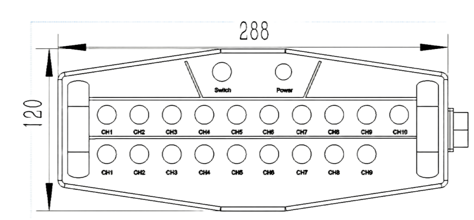
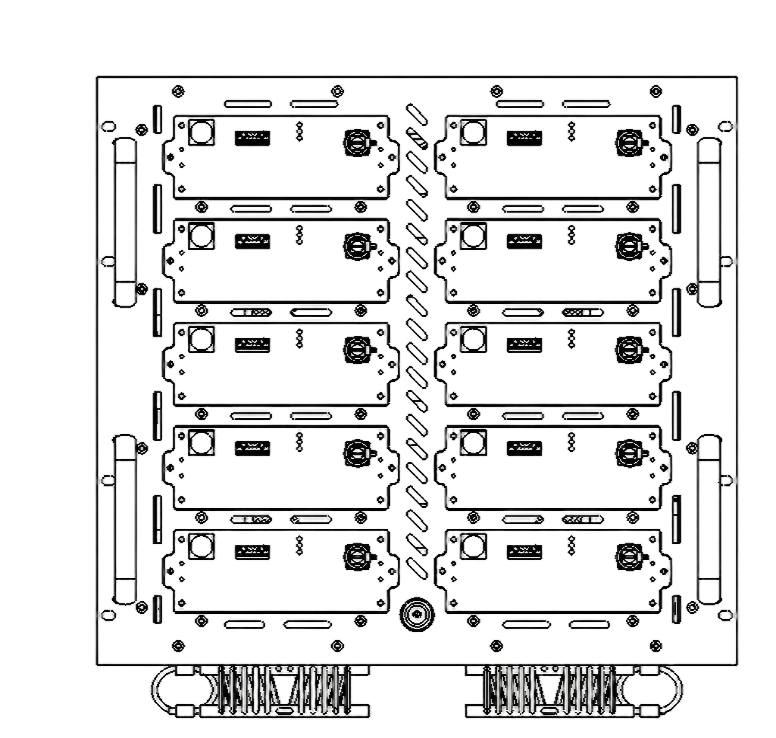
4.2 Schematic Diagram of Control Box


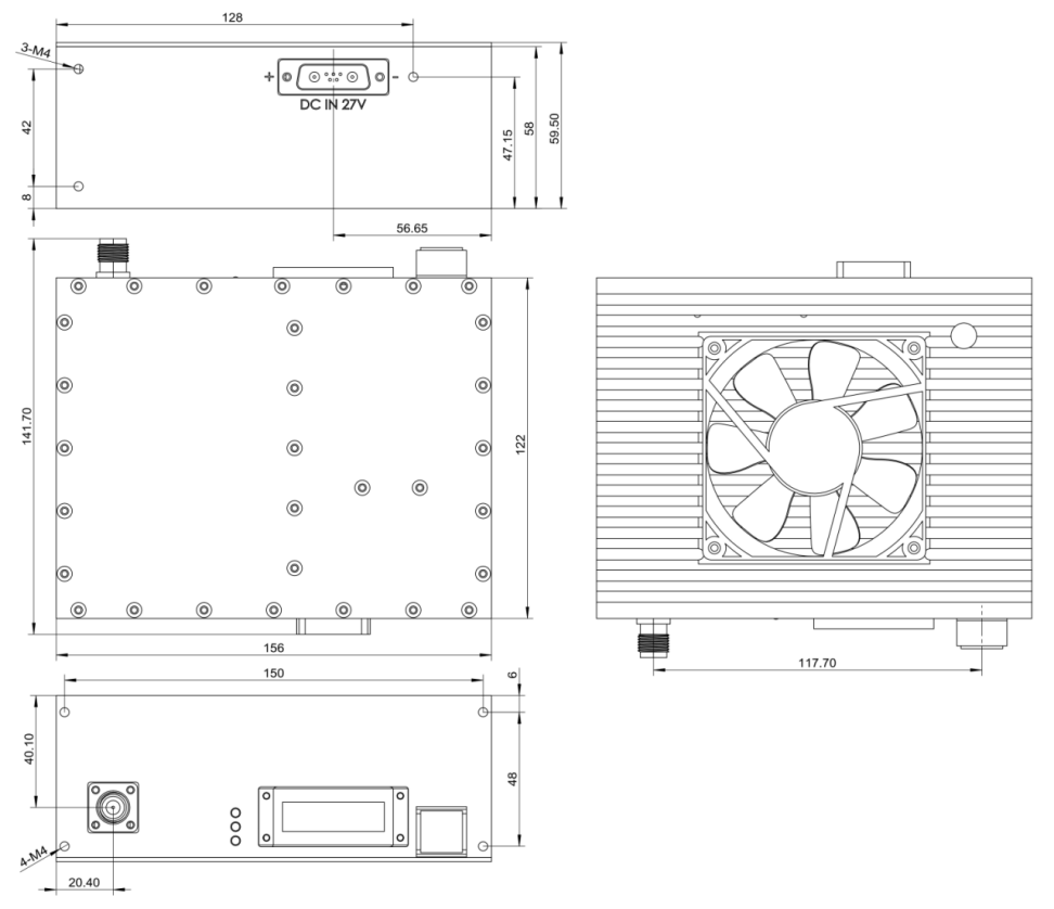
4.3 Schematic Diagram of Module
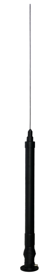
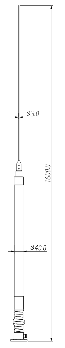
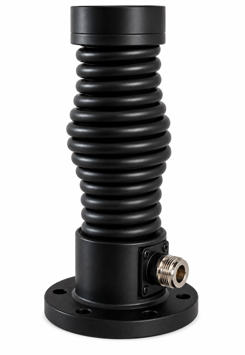
4.4 Schematic Diagram of Omnidirectional Antenna
Interference Band
Full-Band Countermeasure — 19 independent channels covering 100 MHz to 6 GHz:
| Channel | Frequency Band (MHz) | Coverage | Power (W) |
|---|---|---|---|
| CH 1 | 135 – 175 | VHF / Tactical Comms | 100 W |
| CH 2 | 400 – 470 | UHF / Walkie-talkie | 100 W |
| CH 3 | 450 – 480 | UHF Band | 100 W |
| CH 4 | 600 – 680 | 600 MHz Band | 100 W |
| CH 5 | 720 – 800 | 700/800 MHz Band | 100 W |
| CH 6 | 780 – 840 | 800 MHz Band | 100 W |
| CH 7 | 910 – 980 | GSM 900 / 2G | 100 W |
| CH 8 | 1160 – 1280 | GPS L1/L2 | 100 W |
| CH 9 | 1790 – 1900 | 1800 MHz / LTE | 100 W |
| CH 10 | 1560 – 1630 | GPS / GLONASS | 100 W |
| CH 11 | 2100 – 2180 | WCDMA / 3G | 100 W |
| CH 12 | 2290 – 2410 | 2.4 GHz Lower | 100 W |
| CH 13 | 2400 – 2500 | WiFi / BT / Drone | 100 W |
| CH 14 | 2500 – 2700 | LTE Band 41 | 100 W |
| CH 15 | 3400 – 3600 | 5G Sub-6 GHz | 100 W |
| CH 16 | 3600 – 3800 | 5G NR Band | 100 W |
| CH 17 | 3800 – 4000 | 5G / C-Band | 100 W |
| CH 18 | 5150 – 5350 | WiFi 5 GHz Low | 100 W |
| CH 19 | 5720 – 5880 | WiFi 5 GHz High / Drone | 100 W |
Complete Parameter
6.1 Essential Parameters
| Parameter | Specification |
|---|---|
| Dimensions | 482 × 426 × 480 mm (single chassis, incl. vehicle mount base, excl. antenna) |
| Weight | ≤ 40 kg (per chassis unit, incl. vehicle mount base, excl. antenna) |
| Chassis Color | Ash black |
| Material | Aluminum alloy |
| Application Method | Vehicular |
| Power Supply Mode | Main power supply AC 220 V |
| Total Current | 15 A (total for two chassis, operating at full load) |
| Total Power | 1,900 W (total for two chassis at full load) |
| Communicating Protocol | TCP protocol, 485 protocol |
| Interface Type | Network interface, 24-pin control interface, power supply interface |
| Antenna Type | Omni-directional high-gain strike spring antenna |
| Jamming Angle | Horizontal: 360°; Vertical: 17° |
| Jamming Distance | 20 m – 5 km (open line-of-sight) |
| Working Temperature / Humidity | −30 °C to +65 °C / ≤ 80% |
| System Reliability | MBTF no less than 1,000 hours |
| System Response Time | No more than 30 seconds (startup to normal operation) |
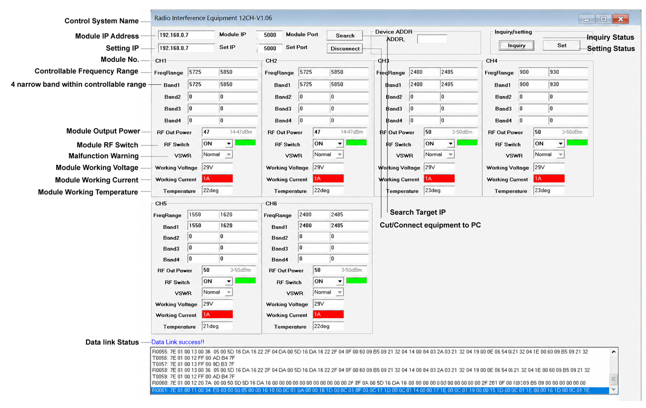
| Supporting Software | Radio Interference Equipment 12CH V1.06 |
| Factory Configuration | Host 1: IP 192.168.0.7 / Port 5000 / ADDR 1 | Host 2: IP 192.168.0.8 / Port 5000 / ADDR 2 |
6.2 Impact Module Parameters
| Parameter | Specification |
|---|---|
| Signal Source | Analog |
| Weight | 1.6 kg (per unit) |
| Interface | Power Supply and Communication: DB7W2 |
| Output Connector | N-Female |
| Communication Mode | 485 communication |
| Heat Dissipation | Equipped with heat dissipation teeth and fan |
| Working Voltage | 24 – 28 V |
| Working Temperature | −30 ~ +65 °C |
| Interference Effect | < 3 seconds |
| Function Protection | Temperature control protection, reflection protection |
| Strike Frequency | Customizable |
| Impact Power | Customizable |
| Power Regulation | Power output adjustable via software: 10 – 100 W (typically 100 W) |
6.3 Antenna Parameters
6.3.1 Low-Frequency Antenna (20 – 100 MHz)
| Parameter | Specification |
|---|---|
| Frequency Range | 20 ~ 100 MHz |
| Gain (Typical) | −5 dBi |
| Antenna Pattern | Omnidirectional |
| Antenna Type | Unipole |
| Horizontal Wavefront Width | 360° |
| VSWR | ≤ 3.0 |
| Polarization Form | Perpendicular |
| Power Capacity | 100 W |
| Input Resistance | 50 Ω |
| Connector Type | N-Female |
| Working Temperature | −30 ~ +65 °C |
| Installation Method | Flange installation |
6.3.2 Intermediate Frequency Antenna (2400 – 2500 MHz)
| Parameter | Specification |
|---|---|
| Frequency Range | 2400 – 2500 MHz |
| Gain | 6 ± 1 dBi |
| VSWR | ≤ 2.0 |
| Polarization Mode | Perpendicular |
| Horizontal Wavelet Width | 360° |
| Vertical Flap Width | 23 ± 5° |
| Out-of-Roundness | ± 2 dB |
| Input Resistance | 50 Ω |
| Maximum Power | 100 W |
| Connector Type | N-Female |
| Lightning Protection | DC grounding |
| Working Temperature | −30 ~ +65 °C |
| Installation Method | Flange installation |
6.3.3 High-Frequency Antenna (5720 – 5880 MHz)
| Parameter | Specification |
|---|---|
| Frequency Range | 5720 – 5880 MHz |
| Gain | 8 ± 1 dBi |
| VSWR | ≤ 1.8 |
| Polarization Mode | Perpendicular |
| Horizontal Wavelet Width | 360° |
| Vertical Flap Width | 17 ± 3° |
| Out-of-Roundness | ± 2 dB |
| Input Resistance | 50 Ω |
| Maximum Power | 100 W |
| Connector Type | N-Female |
| Lightning Protection | DC grounding |
| Working Temperature | −30 ~ +65 °C |
| Installation Method | Flange installation |
Packing List
| Product | Qty | Size / Spec | Image |
|---|---|---|---|
| Host 1 | 1 | 482×426×480 mm (L×W×H) | 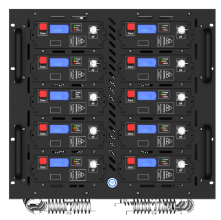 |
| Host 2 | 1 | 482×426×480 mm (L×W×H) | 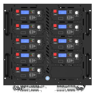 |
| AC Power Cord | 2 | 1.8 m | 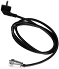 |
| Ethernet Cable | 2 | 3 m | 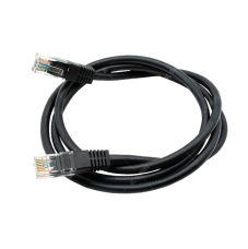 |
| 24-Core Aviation Control Line (No.1) | 1 | 5 m | 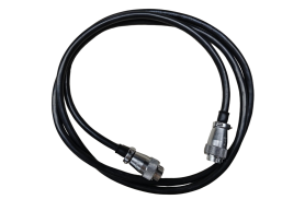 |
| 24-Core Aviation Control Line (No.2) | 1 | 2 m | |
| Keyboard Actuator Box | 1 | 288×120×45 mm | 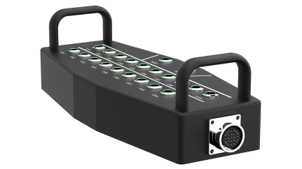 |
| Vehicle Base | 16 | 127×47×38 mm | 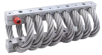 |
| Omnidirectional Spring Antenna | 19 | — | 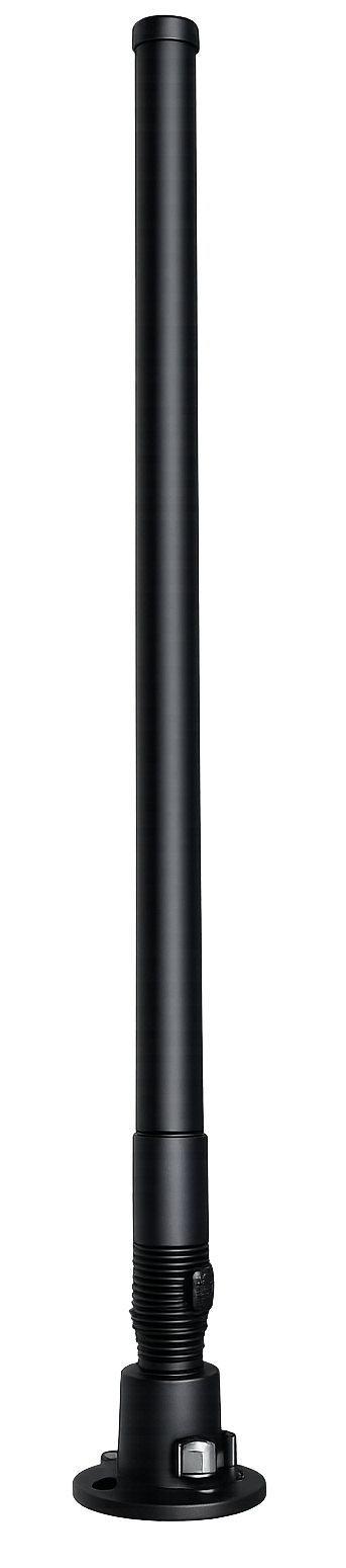 |
| Feeder Line | 19 | 3 m | 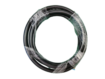 |
Complete Machine & Accessories Description
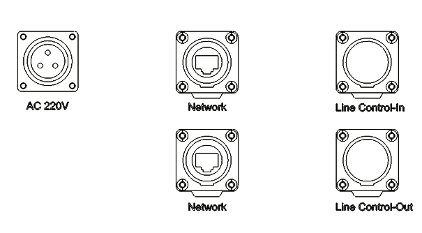
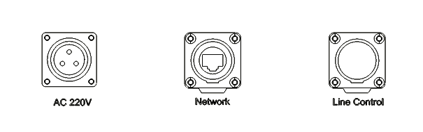
8.1 Host Device 1 – Interface Description
| # | Interface Name | Specification |
|---|---|---|
| 1 | AC 220V | 220V AC power socket for equipment |
| 2 | Network | Network communication interface |
| 3 | Line Control-In | 24-pin control interface (for Line Control of Host Device 2) |
| 4 | Line Control-Out | 24-pin control interface (wiring control box) |
| 5 | N-Female | Anti-jamming antenna interface |
| 6 | Power Button | Power switch for the complete equipment |

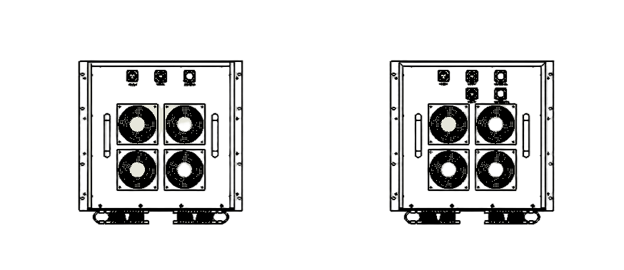
8.2 Host Device 2 – Interface Description
| # | Interface Name | Specification |
|---|---|---|
| 1 | AC 220V | 220V AC power socket for equipment |
| 2 | Network | Network communication interface |
| 3 | Line Control | 24-pin control interface (from Line Control-In of Host Device 1) |
| 5 | N-Female | Anti-jamming antenna interface |
| 6 | Power Button | Power switch for the complete equipment |
Host Device 2 – Panel Overview
8.3 Button Line Control Box – Description
| # | Interface Name | Specification |
|---|---|---|
| 1 | CH1 – CH10 | Power supply switches for various modules on Host 1 |
| 2 | CH1 – CH9 | Power supply switches for various modules on Host 2 |
| 3 | Switch | Line control box main switch |
| 4 | Power LED | Main switch indicator light |
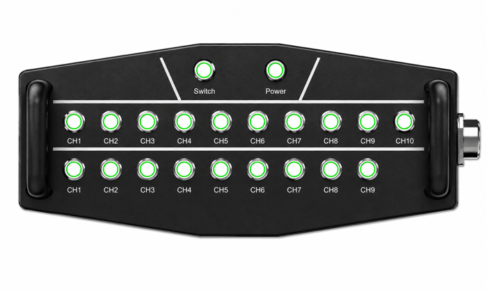
Button Line Control Box
8.4 Vehicle Base Installation
Vertical Compression Support, Fixed Hole Position M8.
8.5 Module Operation Instructions & Replacement Notes
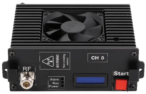
8.5.1 Module Work Instructions
| # | Name | Explanation |
|---|---|---|
| 1 | Start | Module switch (RF transmission switch; pressing it will display a red backlight indicator) |
| 2 | Display Screen | Module display screen for frequency band, power, and switch status |
| 3 | Power | Power supply indicator light (red) |
| 4 | Run | Module operational status indicator light (green) |
| 5 | Alarm | Reflection alarm indicator light (yellow) |
| 6 | RF | Feedline connector |
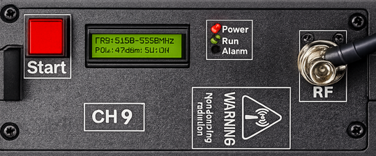
Module Front Panel – Indicator Layout
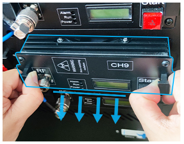
8.5.2 Replacement Note
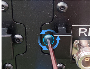
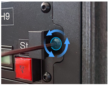
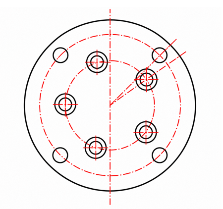
8.6 Antenna Installation
Figure 1 shows the N-type RF connector connected to the feeder line. Figure 2 illustrates the antenna mounting hole positions.
8.7 Definition of 24-Core Control Core
| # | Pin Name | Explanation |
|---|---|---|
| 1 | 1 ~ 10 | Control of modules CH1 to CH10 corresponding to Host 1 |
| 2 | 11 ~ 19 | Control of modules CH1 to CH9 corresponding to Host 2 |
| 3 | 23 | Total switch control: 28V+ |
| 4 | 24 | GND |
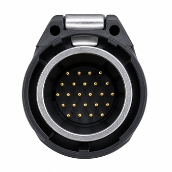
24-Core Control Connector – Pin Reference
Attention
-
9.1 Unboxing Inspection
Inspect the major equipment and accessories listed above. If any components are missing, contact the equipment supplier to ensure proper operation of this product.
Verify the number of antennas and their markings — confirm whether they correspond one-to-one with the host module.
-
9.2 Antenna Installation
During routine use, directly screw the component onto the machine according to the labeled specifications to ensure secure fixation.
Low-frequency band antennas tend to be longer in length. For automotive applications, they are typically recommended to be installed at the rear of the vehicle.
High-frequency antennas are typically mounted on the vehicle roof. It is recommended to use an antenna bracket with a folding mechanism, allowing the antenna to be folded back onto the roof when not in use.
The antenna must be securely fixed, and the connection between the antenna and the host unit or through the feeder must be tightened to the maximum extent.
Off-road vehicle modification is generally recommended as the primary approach.
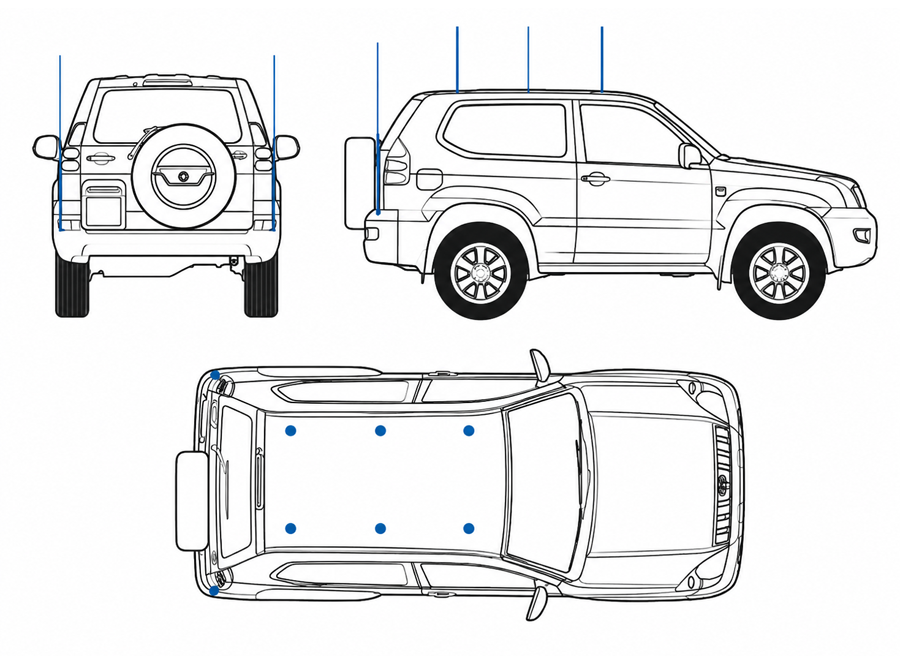
Vehicle Installation Reference
-
9.3 Heat Dissipation & Ventilation
This device features intelligent heat dissipation and ventilation systems, with the equipment ventilation outlets located on the side panels.
During vehicle modification, additional cooling and ventilation systems should be implemented.
Operation and Usage Instructions
- Install antennas matching the frequency specified in the factory configuration. Connect the feeder line to the corresponding antenna interface of the host.
- The two ends of Control Line 1 are connected to the Line Control-out of Line Control Box and Host 1's Line Control-out respectively; Control Line 2 connects from the line control-out of Host 1 to Host 2's Line Control interface.
- Connect both ends of Network Cable 1 to Host 1's Network port and Host 2's Network port, respectively.
- Connect both hosts to the 220V power supply port.
- Press all buttons on the wire control box.
- Turn off the power switches for Host 1 and Host 2 respectively.
- The backlight of power switches on Host 1 and Host 2 illuminates; all button backlights on the line control box light up, along with the Power indicator light; all module display screens and Power indicator lights activate, and the cooling fans commence operation.
Software Description
Local Ethernet Settings
On a PC, open Control Panel → Network Connections → right-click Ethernet → Properties → Internet Protocol (IPv4) → Manual IP assignment:
| Host | IP Address | Port | ADDR |
|---|---|---|---|
| Host 1 (Factory default) | 192.168.0.7 | 5000 | 1 |
| Host 2 (Factory default) | 192.168.0.8 | 5000 | 2 |
Connecting to the Software
Click to open Radio Interference Equipment 12CH V1.06. For Host 1, set IP to 192.168.0.7, port: 5000, ADDR: 1. For Host 2, set IP to 192.168.0.8, port: 5000, ADDR: 2.
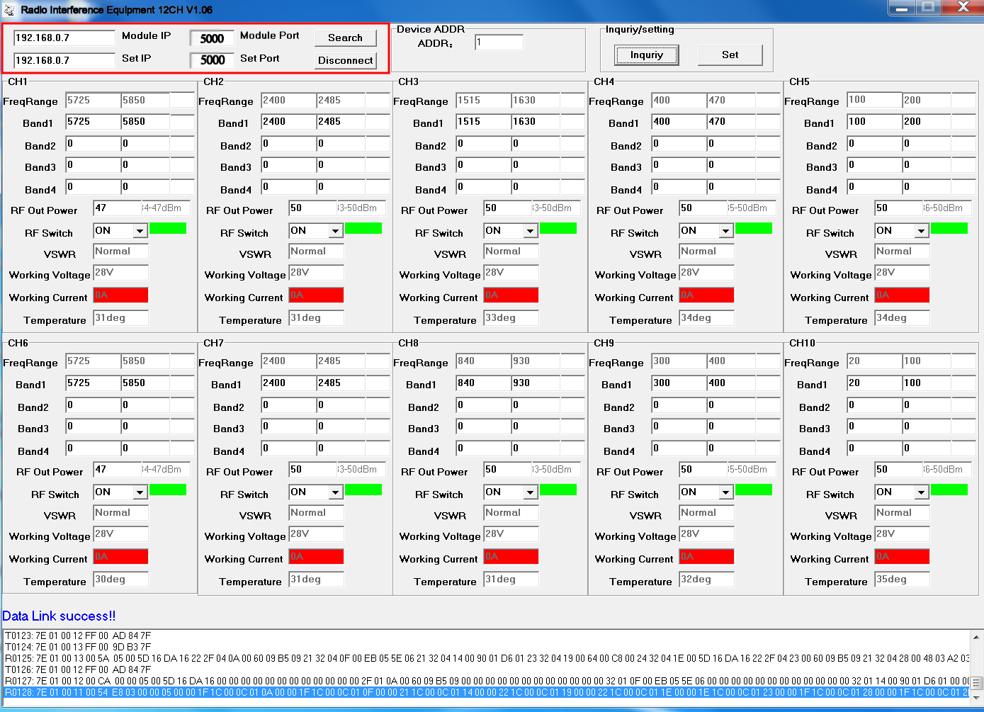
After successful connection, click Inquiry to read data (there may be a delay; click Inquiry several times if needed). Data Link success! will appear at the bottom, indicating a successful connection.
If RF Switch shows ON, Working Voltage shows 26V–28V, and Working Current shows red 0A (no current) — this indicates no load or antenna is connected.
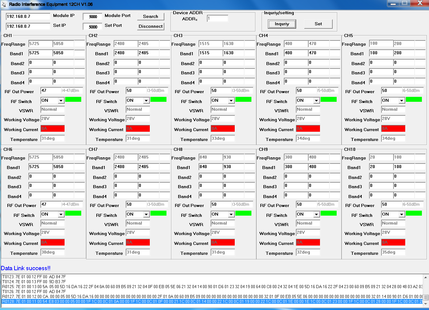
After connecting a load or antenna, Working Current will display the module's operating current.
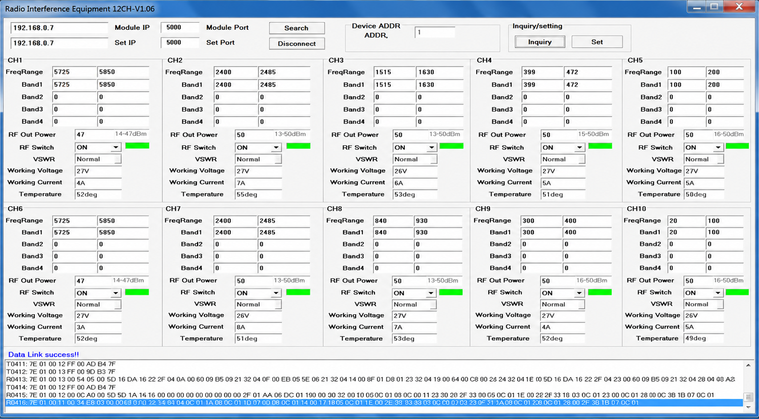
You can adjust the output power and switch status of each module. The master equipment address code defaults to 1; no modification is needed.
Software Module Function Reference